MBSE FAQ: What is MBSE?, What is SysML? Why use MBSE?
Please contact us with your constructive ideas to correct and improve this section.
General Questions
What is Model-Based Systems Engineering (MBSE)?
Question Variant(s): What is MBSE?; What is Model-Based Systems Development (MBSD)?; What is Agile MBSE?
Model-Based Systems Engineering (MBSE), a.k.a. Model-Based Systems Development (MBSD), is a Systems Engineering process paradigm that emphasizes the application of rigorous architecture modeling principles and best practices to Systems Engineering activities throughout the System Development Life Cycle (SDLC). These Systems Engineering activities include, but are not limited to, requirements analysis, functional analysis, performance analysis, system design, trade studies, system architecture specification, and system Verification & Validation (V&V).
According to the INCOSE SEBoK (Systems Engineering Book of Knowledge) MBSE may be considered a "subset of digital engineering".
Why use a Model-Based Systems Engineering (MBSE) approach?
Question Variant(s): What is MBSE used for?
If you are a Systems Engineer and want to improve the precision and efficiency of your communications with fellow Systems Engineers and other system and business stakeholders (e.g., Clients, Software Engineers), then you should consider using an architecture modeling language standard as a lingua franca (common language). The most popular choice for MBSE applications is the SysML dialect of UML 2, which extends the UML standard for software-intensive applications so that it can be applied to Systems Engineering applications.
Here's a list of reasons why Systems Engineers may want to use a Model-Based Systems Engineering (MBSE) approach with a common architecture modeling language such as SysML for their mission-critical work:
- Facilitate communication among various stakeholders across the System Development Life Cycle (SDLC), including both sides of System V-Model;
- Capture and manage corporate Intellectual Property related to system architectures, analyses, designs, and processes;
- Facilitate Trade Studies and compare and contrast “As Is” and “To Be” solutions;
- Provide scalable structure for problem solving;
- Furnish rich abstractions to manage size and complexity;
- Explore multiple solutions or ideas concurrently with minimal risk; and
- Detect errors and omissions early in System Development Life Cycle (SDLC)
Of course, like any technology, MBSE can be both properly applied and abused. Compare and contrast the difference between "SysML-as-Pretty-Pictures" and "SysML-as-System-Architecture-Blueprint" usage modes in the SysML FAQ: How should SysML be applied to an MBSE project? How is SysML commonly abused?.
Who created Model-Based Systems Engineering (MBSE)?
Question Variant(s): Who created MBSE?
Model-based specification and simulation techniques have been associated with Systems Engineering since its inception as an interdisciplinary field of engineering, which can be traced to work at Bell Telephone Laboratories and the US Department of Defense (DoD) during the 1940s (WWII).
The first known public use of the term "Model-Based Systems Engineering" was by A. Wayne Wymore in his 1993 book, which used the terms as its title [Wymore 1993]. The MBSE term was also commonly used within the SysML Partners consortium during the formative years of their Systems Modeling Language (SysML) open source specification project during 2003-2005. Some SysML Partners used the term order to further differentiate SysML from its parent language UML v2, which was software-centric and associated with the term Model-Driven Development (MDD). Stated succinctly as an analogy:
SysML :: Model-Based Systems Engineering (MBSE) :: UML : Model-Driven Development (MDD)
The SysML Partners published the SysML 1.0 Alpha open source specification in November 2005, and the Object Management Group adopted a variation as OMG SysML 1.0 in 2006. The standardization of SysML resulted in widespread tool support for the new system architecture modeling language standard and associated MBSE processes that emphasized SysML as their lingua franca. For example, PivotPoint Technology Corp., one of the founding members of the SysML Partners, released commercial training courseware in July 2007 that featured Model-Based Systems Engineering with SysML.
In September 2007, the MBSE approach was further generalized and popularized when INCOSE introduced its MBSE 2020 Vision, which was not restricted to SysML, and supported other competitive modeling language standards, such as AP233, HLA, and Modelica. According to the MBSE 2020 Vision: "MBSE is expected to replace the document-centric approach that has been practiced by systems engineers in the past and to influence the future practice of systems engineering by being fully integrated into the definition of systems engineering processes."
According to the INCOSE SEBoK (Systems Engineering Book of Knowledge) MBSE may be considered a "subset of digital engineering".
For a longer and more thorough explanation of the relationships among Model-Based Systems Engineering, Model-Based Engineering, and related MBE subdisciplines, check out the Model-Based Engineering Forum and the Model-Based Engineering Visual Glossary.
What is the Systems Modeling Language (SysML)?
Question Variant(s): What is SysML?; What is OMG SysML?
Definition
Systems Modeling Language (SysML): SysML is a general-purpose architecture modeling language for Systems Engineering applications.
- SysML supports the specification, analysis, design, verification, and validation of a broad range of systems and systems-of-systems. These systems may include hardware, software, information, processes, personnel, and facilities.
- SysML is a dialect of UML 2, and is defined as a UML 2 Profile. (A UML Profile is a UML dialect that customizes the language via three mechanisms: Stereotypes, Tagged Values, and Constraints.)
- SysML is an enabling technology for Model-Based Systems Engineering (MBSE).
The SysML was originally created by the SysML Partners' SysML Open Source Specification Project in 2003. The SysML was adapted and adopted by the Object Management Group (OMG) as OMG SysML in 2006. For more information about the current version of OMG SysML, see the SysML FAQ: What is the current version of SysML?.
SysML Diagram Taxonomy
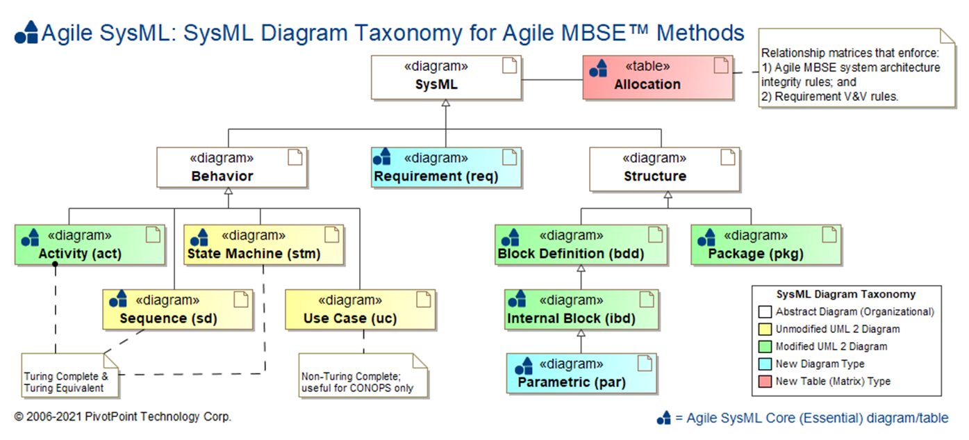
The SysML is composed of nine (9) diagram types and Allocation Tables for mapping language elements across diagram types:
| Diagram Name | Diagram Type | UML 2 Analog | SDLC Usage | Essential AGILE SYSML? |
Dynamic Sim † |
Math Sim ‡ |
Auto Code Gen |
Rigor | Semi | Informal |
|---|---|---|---|---|---|---|---|---|---|---|
| Requirement diagram (req) | Static Structure [Declarative] |
N/A | Requirements Analysis | |||||||
| Use Case diagram (uc) | Behavior * [Non-Simulatable] |
Use Case | Requirements Analysis | |||||||
| Activity diagram (act) | Dynamic Behavior [Simulatable] |
Activity [minor mods] |
System Analysis, Functional Analysis, System Design |
|||||||
| Sequence diagram (seq) | Dynamic Behavior [Simulatable] |
Sequence | System Design | |||||||
| State Machine diagram (stm) | Dynamic Behavior [Simulatable] |
State Machine | System Analysis, System Design |
|||||||
| Block Definition Diagram (bdd) | Static Structure [Black Box Definition] |
Class [moderate mods] |
System Analysis, System Design |
|||||||
| Internal Block Diagram (ibd) | Static Structure [White Box Usage] |
Composite Structure [moderate mods] |
System Analysis, System Design |
|||||||
| Parametric Diagram (par) | Static Structure [White Box Usage] |
N/A | System Analysis, System Design |
|||||||
| Package diagram (pkg) | Static Structure [Grouping] |
Package [minor mods] |
All SDLC phases | |||||||
| Allocation Table | N/A [Relationship Matrix] |
N/A | All SDLC phases | |||||||
†: Dynamic Simulation (a.k.a. Dynamic System Simulation) refers to the capability of a computer program to execute the time-varying behavior of a system of interest. In general, with the exception of Use Case diagrams, SysML and UML 2 Behavior diagrams are potentially capable of Dynamic System Simulation.
‡: Mathematical Modeling & Simulation (a.k.a. Mathematical ModSim, Mathematical M&S, Parametric Simulation) refers to the capability of a computer program to execute the a mathematical model of the behavior of a system of interest, where the model is defined as a set of mathematical equations. When properly defined and applied, Parametric diagrams are capable of Mathematical ModSim; no other SysML or UML 2 diagrams are capable of this.
*: Although Use Case diagrams are generally classified as Behavior diagrams by both the OMG SysML and UML 2 specifications, their Behavioral semantics are ambiguous and incomplete. Whereas Activity, Sequence, and State Machine diagrams are Turing Complete, and their dynamic behavior can be simulated or executed, Use Cases diagrams are not Turing Complete and are not simulatable.
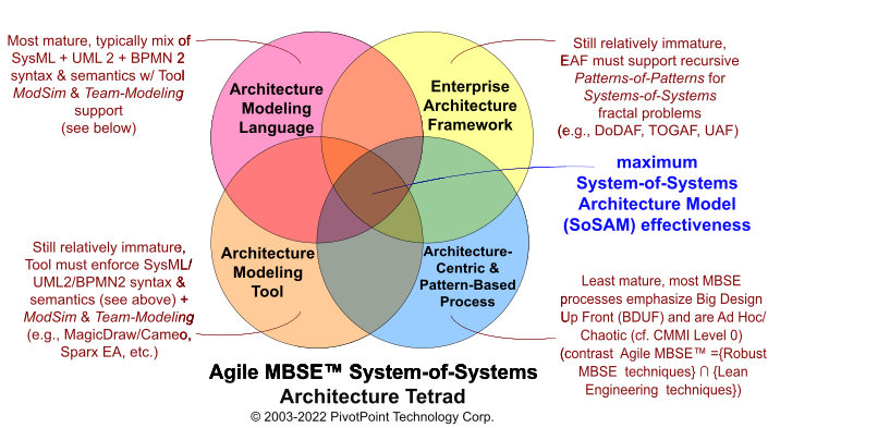
Bitter experience has show that MBSE projects that fail to properly balance the four parts of the System Architecture Tetrad tend to achieve poor or mixed results.
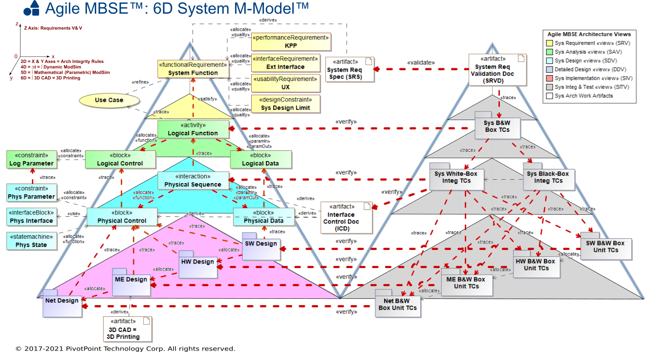
Since the terms "verification" and "validation" are commonly conflated among systems and software engineers, we first clarify the differences between them using Boehm's classic formal and informal definitions [Boehm 84]:
A. DefinitionsVerification - to establish the truth of the correspondence between a software product and its specification. (Note: This definition is derived from the Latin word for "truth," veritas. Note also that data bases and documentation are fit subjects for verification, as well as programs.)
Validation - to establish the fitness or worth of a software product for its operational mission. (Note: This definition is derived from the Latin word for "to be worthy," valere.)Informally, we might define these terms via the following questions:
Verification: "Am I building the product right?"
Validation: "Am I building the right product?"— [Boehm 84] Guidelines for Verifying and Validating Software Requirements and Design Specifications
Requirement Validation is typically the responsibility of system Stakeholders, who review Requirement specifications (e.g., SysML Requirement diagrams) to determine that they define "the right product" to be built. Requirement qualities checked during Validation include, but are not limited to, the following: Correctness, Completeness, Consistency, Clarity (Unambiguousness), Conciseness, Feasibility, Necessity, and Prioritization.
- SysML Support for Requirement Validation: SysML supports Requirement Validation by defining Requirements as first class visual modeling elements that can be classified (e.g., Functional, Performance, Interface, Design Constraints), organized into hierarchies (via Containment relationships), and assigned properties (TaggedValues) as needed (e.g., Risk, VerifyMethod, Priority, Level-of-Effort).
Requirement Verification is typically the responsibility of System Engineers and Systems Analysts, who (as per [Boehm 84]) "establish the truth of the correspondence between" the systems engineering product and its Requirement specification.
- SysML Support for Requirement Verification: SysML primarily supports Requirement Verification via two complementary relationships:
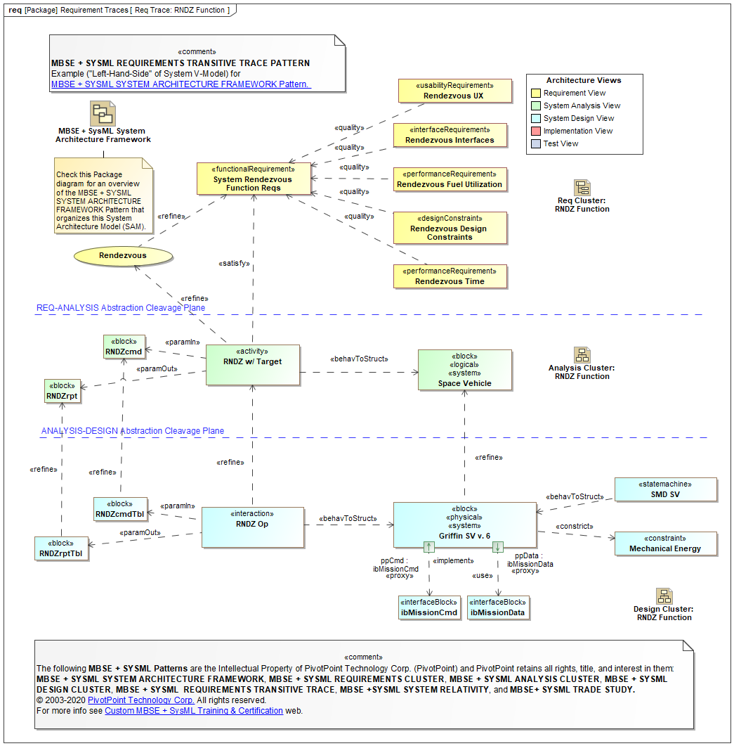
- Satisfy («satisfy») dependency: The client model element fulfills a supplier Requirement. (See example.)
- Verify («verify») dependency: The client TestCase («testCase») determines whether a supplier Requirement has been fulfilled. (See example.)
Another Requirement Verification best practice is to define a VerifyMethod property (TaggedValue) for Requirements with appropriate values (e.g., Analysis, Demonstration, Inspection, Test).
In order to increase your likelihood of achieving SysML language fluency, you may want to consider a multi-pronged approach to learning SysML. For example, if you have the opportunity, you may want to start off with basic SysML hands-on training, followed up by expert coaching (mentoring) for On The Job training, which in turn is followed up with advanced SysML hands-on training. For the best learning experience, ensure that all your SysML training is taught by expert practitioners with extensive application experience on large projects, and includes frequent hands-on practice sessions and Q&A sessions.
In addition, you should also read voraciously about SysML techniques and best practices, so that you can further benefit from the experience (and mistakes) of others.
You can find a listing of selected MBSE + SysML training resources on the MBSE + SysML Training page of this web.
MBSE Tools & Interoperability
TOGAF and ARCHIMATE are trademarks of The Open Group.
ENTERPRISE ARCHITECT is a trademark of Sparx Systems Pty Ltd. MAGICDRAW and CAMEO are trademarks of No Magic, Inc. RATIONAL RHAPSODY is a trademark of IBM.
All other trademarks are the property of their respective owners.
